DRM, Digital Radio Mondiale, is a form of digital radio. Transmissions
are relatively scarce here in Western Europe, but is seems that elsewhere
there is an increasing interest.
While DRM provides the opportunity to transmit more than a single
service (up to 4), most transmissions carry a single one.
The decoder provides a possibility for selecting a service, but - obviously -
for a single service selection is not needed.
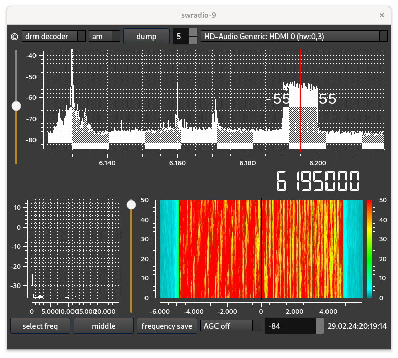
The spectrum of the DRM signal is typical for an OFDM transmission, it looks
like a block.
The signal - in the picture above a Mode B signal contains about
200 carriers, differing in frequency about 45 Hz.
That picture shows the spectrum of the signal and, in the second display, the waterfall. It shows that this is a pretty nice signal, not too much disturbance of amplitude and phase.
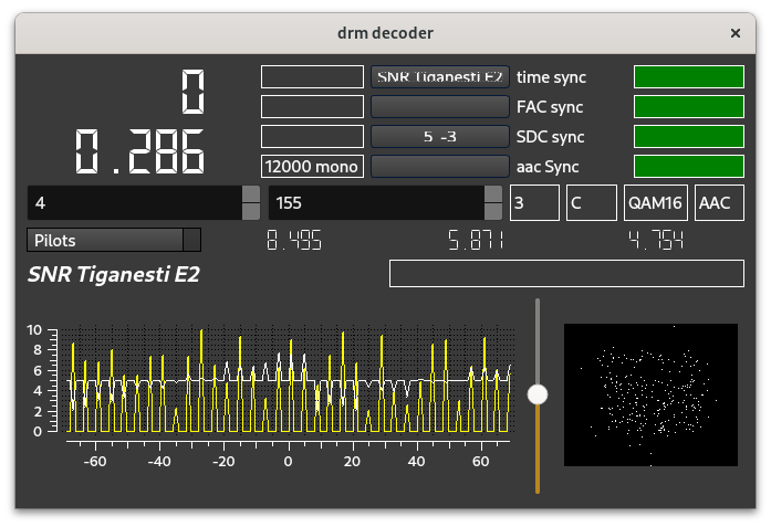
The second picture shows the decoder. The four green labels show that
the synchronization went well, and the signal could be decoded.
The numbers left tell the frequency offset, which - with app a quarter of a Hz -
is small.
The text tells that the transmission is from SNR Tiganesti which
is Romenian, and that the output is a mono signal with a samplerate of 12000.
A DRM signal is - in the time domain - from the point of view of the decoder -
a stream of samples, here sampled with a rate of 12000
(compare that with a DAB stream where we have 2048000 samples/second).
This input stream can be considered to consist of a sequence of
words, where a word is just over 300 samples.
Such a word - when identified in the samplestream - is then adapted
by stripping of the first app 60 samples, after which the 256 samples
are fed through an FFT processor.a
One of the (first) tasks of a decoder is to identify where in the
incoming sample stream the words are located (i.e. start).
FFT processing leads to 256 carriers, of which we the middle 200
(app) contain the useful data.
The big issue with DRM is that further decoding, i.e. mapping the carriers
on bits, is coherent, i.e. the signal should be restored to
as it was when it entered the transmitter.
An equalization process takes place, guided by a number
of carriers where the value as it should be is knowm, the pilots.
The picture above shows the correction that is to be applied to these pilots,
such that they have the value as it should have. In the picture the yellow
arrows show the correction on the amplitude, in white the correction
on the phase.
Once the correction is applied to the pilots, some form of interpolation
can be used to correct the other carriers, the ones containing useful values.
The picture above shows that the signal had a frequency error of 0.286
Hz (which is small), the DRM transmission is in Mode C and spectrum form 3
(which just tells that the signals width is 10 KH), and the transmisison is
from the Romenian site Tiganesti.
The numbers 8.495, 5.871 and 4.754 are quality indicators of the
signal, for resp. the FAC, the SDC and the service contents.
The black square shows the constellation of the signal after decoding,
it seems a little noisy, although the signal itself was pretty good.
The signal in this transmission is QAM16 encoded, i.e.
the value of the carrier that is to be decoded is assumed to be in one of
16 positions. An ideal form of a QAM16 signal is shown in the picture below
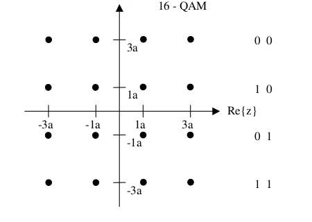
The payload in a DRM signal is in either QAM16 or QAM63 encoded, with QAM16 one single carrier can be mapped onto 4 bits. a QAM64 encoded carrier onto 6 bits. Obviously, in the decoding both amplitude and phase play a role here.
In the path from transmitter to receiver
the signal may be malformed. Fading, caused by atmospheric conditions and
other forms of reflections are the culprit here.
These "channel" effects have to be reversed - as mentioned above -
in the receiver. Using the transformations of the channel on the pilots,
this "channel effect" can be defined as a filtering on the transmitted
signal. This "equalizing" takes some programming effort.
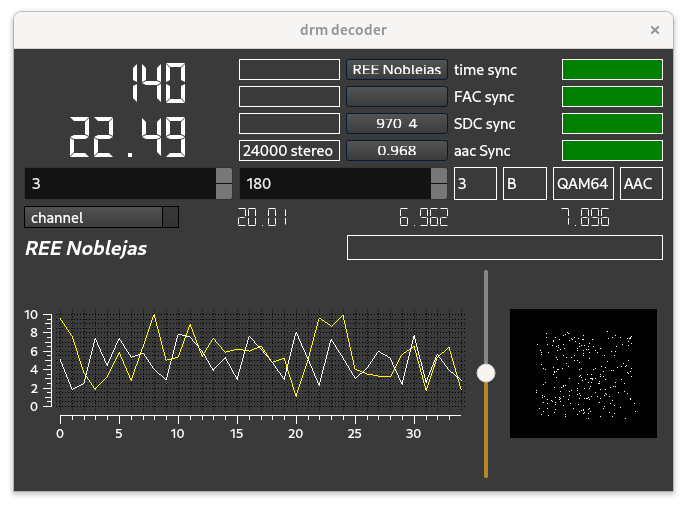
The picture below, this time from a a recording of a transmitter that stopped
transmitting a decade ago - shows the filter parameters that were apparently
applied on the signal from transmitter to receiver, as derived from the
transformation on the pilot. Note btw that the signal here is QAM64 encoded.
The DRM decoder is one of the decoders of the sw-radio.
The sw-radio is a relatively simple piece of software,
it controls a hardware device (i.e. tuning, shifting the frequency and
AD conversions), shows a sectrum of the incoming data,
decimates the incoming samplestream to 12000 samples/second and passes them
on the a selected decoder.
Since the software focuses on shortwaves, devices that can handle
sw frequencies are handled, i.e. SDRplay RSP devices, hackrf and - with
special libraries, some dabsticks. Of course file input of ".wav" files
is also supported.
The software has built-in a number of decoders, while the "front end" does the control of the input device, i.e. setting samplerate, frequency and gain, the decoders get in a sample stream with a rate of 12000 S/s. The simplest decoder takes half a page of code, the most complex one (the drm decoder) takes over 10000 lines of code.
ssb, with selection for usb or lsb;
psk, with a wide selection of modes and settings and with a visual tuning aid;
rtty, with a wide selection of modes and settings;
cw, with (almost) automatic selection of speed and a visual tuning aid;
drm, limited to 10 k bandwidth;
navtex (amtor), with a wide selection of options;
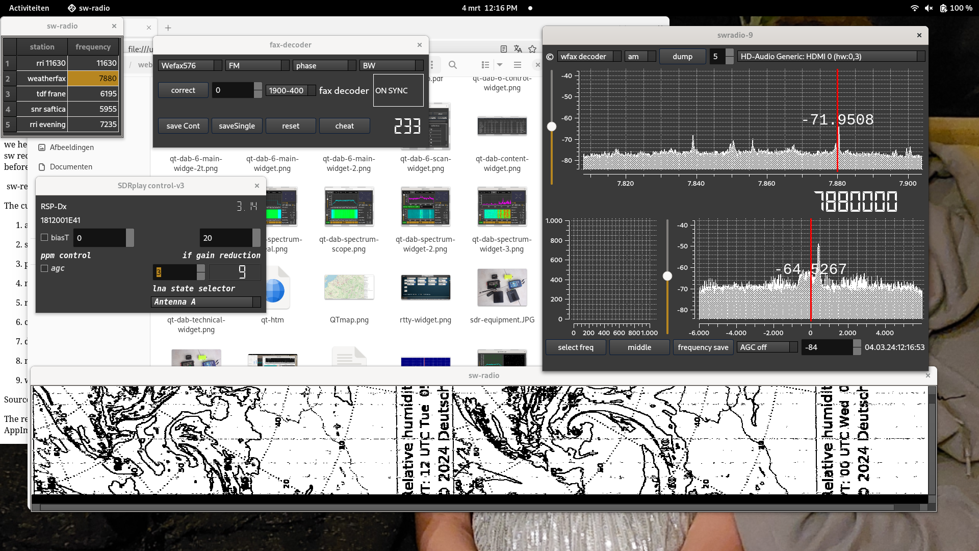
weatherfax decoder, with selection of a variety of settings.
an ft8 decoder, with selection of a variety of settings.
Sources for the sw receiver (and a windows installer) are to be
found
here .
The releases section of this repository contains - next to the sources -
a Windows installer and a for Linux-x64 an AppImage.